- Home
- About Us
- Blog
- Capabilities
Sub-Processes
Plastic Materials
Processes Available
Post Processing
- Contact Us


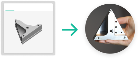
With instant online quotes and rapid production, you can reduce cycle times by as much as 50%.

Tap into a highly vetted and managed network of the best machine shops world-wide.

Choose between fast and cost-effective options to find the best price.


| Hobbing | Wire EDM | Sinker EDM | |
|---|---|---|---|
| Tolerance level | ISO grade 6 to 12 | ISO grade 7 to 12 | ISO grade 8 to 12 |
| Part size | Min: 1.0×1.0x0.3mm Max :500x500x800mm | Min: 3.0×3.0x0.3mm Max: 300x300x200mm | Min: 3.0×3.0x0.3mm Max: 200x200x150mm |
| Top use cases | External gears | External gears, shafts with gears, helical gears | Internal gears and features which are not through hole, internal features requiring minimal fillets such as a hexagonal shaped cutouts in a part |
| Materials | All available materials | All available metal materials | All available metal materials |
| Minimum fillet radius | n/a | 0.05mm standard 0.01mm premium precision | 0.05mm standard 0.01mm premium precision |
| Lead time | As fast as 12 days | As fast as 7 days | As fast as 7 days |


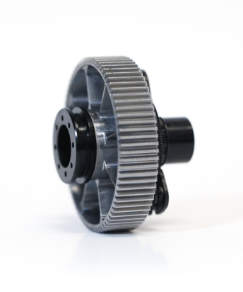
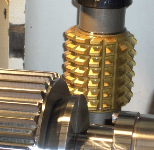
Hobbing is a machining process for cutting gear features on both metal and non-metal parts. The gear teeth (or splines) are progressively cut into a cylindrical piece of material by a series of cuts made by a cutting tool called a hob. Hobbing allows you to achieve various gear shapes and sizes such as spur gears, worm gears and bevel gears. Although gear hobbing can be used for prototyping small quantities, this process is best suited for higher volume production.
Our manufacturing partners have various hobbing tools in stock which allow for quick turnaround times. If a custom gear profile is desired that is not part of our standard hobbing tool library, customers can order custom hobbing tools to be built. If you want to create internal gear features, we offer Electrical Discharge Machining (wire and sinker), as internal gear features cannot be achieved with hobbing.
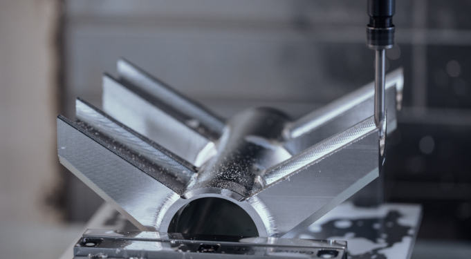
The CNC milling process involves a rotating tool that carves away excess material from a stationary workpiece.
CNC turning uses a rotating workpiece, typically used to make cylindrical parts.
A 5-axis CNC milling machine can move a cutting tool in 5 axes, which allows the operator to simultaneously hit five different sides (or more) of a part depending on the design complexities. Resultantly, the tool is highly capable of creating highly complex products and parts.
With a 5-axis machine, the X, Y, and Z-axes are similar to a 3-axis machine layout. The table then rotates along the A-axis, as it does with the 4-axis. However, the 5-axis machine involves the pivoting action at the joint of the table, followed by rotation along the C-axis, which defines the fifth movement.
A CNC router moves the spindle around a stationary table and is primarily designed to operate at high speeds.
A CNC mill typically moves the workpiece along a linear axis, making cuts through the driving force of rotational speed.
The most commonly used materials in CNC milling are metals, such as aluminum, brass or steel and plastics such as ABS, acrylic, polycarbonate, and polypropylene.